RoboImplant
Hardware
→ Browse this directory on GitHub
· pcb/
· enclosure/
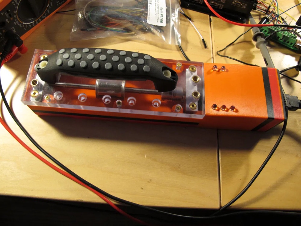 |
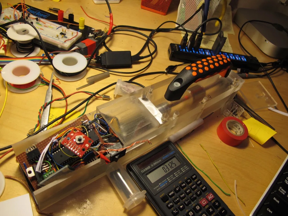 |
| v1 — 3D-printed housing, acrylic top plate, brass inserts and drive coil. | v2 — machined polycarbonate body with the controller electronics integrated alongside the coil assembly. |
The SolidWorks files below model the v1 unit on the left.
pcb/ — controller board
EAGLE 6.1 (CadSoft) design files for the board carrying the ATmega1284P, the DS1267 digital potentiometer, the current/voltage sensing chain, the Bluetooth module, and power management.
| File | |
|---|---|
roboimplantschematic.sch |
Schematic |
roboimplantschematic.brd |
Board layout |
Viewing requires EAGLE 6.x or later (now Autodesk EAGLE / Fusion Electronics). Both files are EAGLE’s XML format. No PDF export, gerbers, drill files, or BOM were produced, so the design is not viewable or manufacturable directly from this repository — exporting a schematic PDF would be the single highest-value addition.
enclosure/ — handheld driver housing
SolidWorks parts and assembly for the housing the clinician holds against the patient.
| File | |
|---|---|
new_controller_enclosure_assembly.SLDASM |
Top-level assembly |
enclosure_bottom.SLDPRT |
Main body |
enclosure_circuit_cover.SLDPRT |
Electronics compartment cover |
enclosure_battery_cover.SLDPRT |
Battery compartment cover |
motor_top_cover.SLDDRW.SLDPRT |
Motor cover |
pcb.SLDPRT |
Board model, for fit-checking |
6mm_rod.SLDPRT |
Rod model |
Requires SolidWorks. No STEP, IGES, STL, or DXF exports were made.
Two known quirks, left as-found rather than tidied:
motor_top_cover.SLDDRW.SLDPRThas a doubled extension from a save-as accident. It is a part file, not a drawing, and opens correctly as one — no.SLDDRWwas ever preserved.- The assembly stores references to its component files by name. If parts are renamed or moved, SolidWorks will report broken references and need them re-pointed.
Motor controller
The board drives a maxon ESCON 36/2 DC servo controller (P/N 403112) via an
analog set-value input. Vendor documentation is in ../docs/motor/;
motor constants used by the firmware are in firmware/config.h.